
Implementing Image Perspective Transformation (Homography) in Delphi — Converting Trapezoid and Parallelogram Regions with Code Examples
This article explains how to perform perspective transformation (homography) in Delphi to correct trapezoid and parallelogram regions in an image.
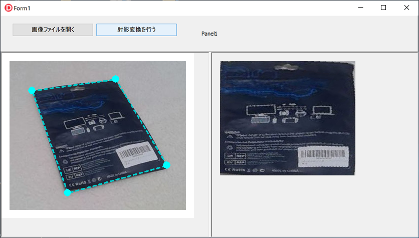
The sample VCL application allows the user to drag control handles on the form to define the transformation area, and then generates the corrected output image.
It also demonstrates how to build the application using VCL components such as TScrollBox and ExtCreatePen, covering the entire workflow from loading JPG/PNG files to applying the transformation.
Using homography, you can convert trapezoidal or parallelogram-shaped regions into a rectangular image.
The bilinear interpolation formula used for the perspective transformation is based on the reference below:
http://aows.jp/imgprc/material/04/
Overview of the Application
The application loads an image in the left pane, allows the user to drag control handles to select a trapezoid or parallelogram region, and then performs a perspective (homography) transformation to generate a rectangular corrected image in the right pane.
Creating a New Delphi Project
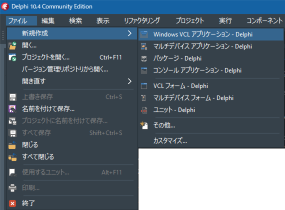
Start the Delphi IDE and select File ⇒ New ⇒ Windows VCL Application – Delphi.
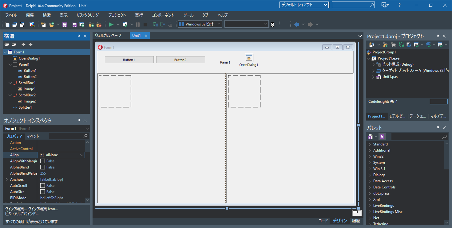
Screen Layout
- Drag and drop a
TOpenDialogcomponent onto the form. - Add a
TPaneland set its Align property to alTop. - Place two
TButtoncomponents on Panel1. - Add a
TScrollBoxto the form and set its Align property to alLeft. - Inside ScrollBox1, place a
TImagecomponent. - Add a
TSplitterto the form. - Add another
TScrollBoxand set its Align property to alClient. - Inside ScrollBox2, place another
TImagecomponent.
Writing the Source Code
Enter the following source code into your project.
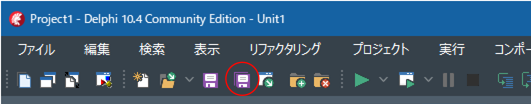
Be sure to save your files frequently using the “Save All” button.
unit Unit1;

interface

uses
  Winapi.Windows, Winapi.Messages, System.SysUtils, System.Variants, System.Classes,
  Vcl.Graphics, Vcl.Controls, Vcl.Forms, Vcl.Dialogs, Vcl.StdCtrls, Vcl.ExtCtrls,
  Vcl.Imaging.Pngimage, Vcl.Imaging.jpeg
  ,System.Math ;

type
  TFourPoint=array[0..3] of TPoint;

  TForm1 = class(TForm)
    ScrollBox1: TScrollBox;
    ScrollBox2: TScrollBox;
    OpenDialog1: TOpenDialog;
    Panel1: TPanel;
    Image1: TImage;
    Image2: TImage;
    Button1: TButton;
    Button2: TButton;
    Splitter1: TSplitter;
    procedure FormCreate(Sender: TObject);
    procedure FormDestroy(Sender: TObject);
    procedure Button1Click(Sender: TObject);
    procedure Button2Click(Sender: TObject);
    procedure Image1MouseDown(Sender: TObject; Button: TMouseButton;
      Shift: TShiftState; X, Y: Integer);
    procedure Image1MouseUp(Sender: TObject; Button: TMouseButton;
      Shift: TShiftState; X, Y: Integer);
    procedure Image1MouseMove(Sender: TObject; Shift: TShiftState; X,
      Y: Integer);
  private
    { Private declarations }
    // Coordinates of the four control handles (rubber-band corners)
    pta: TFourPoint;
    // Temporary coordinates of the control handles while dragging
    tmp_pta: TFourPoint;
    // Loaded image
    mBmp: TBitmap;
    // Mouse position at the moment dragging starts
    MousePoint: TPoint;
    // Index of the control handle currently being dragged
    MousePointNum: Integer;
    // Draws the image, control handles, and rubber-band polygon
    procedure DrawImage(fp: TFourPoint);
  public
    { Public declarations }
  end;

var
  Form1: TForm1;
const
  // Margin of 16 pixels around the image
  // Ensures control handles at the corners are fully visible
  // When loading an image, a bitmap larger by 16px on each side is created
  ImgMargin: Integer = 16;

  // Dragging margin for control handles
  ControlHandleMargin: Integer = 8;
implementation

{$R *.dfm}

// Open an image file
procedure TForm1.Button1Click(Sender: TObject);
var png:TPngImage;
    jpg:TJPEGImage;
    bmp:TBitmap;
    ext:String;
begin
  Image1.Left:=0;
  Image1.Top:=0;
  if not OpenDialog1.Execute then exit;

  ext:=LowerCase(ExtractFileExt(OpenDialog1.FileName));
  if ext='.png' then
  begin
    png:=TPngImage.Create;
    try
      png.LoadFromFile(OpenDialog1.FileName);
      mBmp.Assign(png);
    finally
      png.Free;
    end;
  end
  else if (ext='.jpg') or (ext='.jpeg') then
  begin
    jpg:=TJPEGImage.Create;
    try
      jpg.LoadFromFile(OpenDialog1.FileName);
      mBmp.Assign(jpg);
    finally
      jpg.Free;
    end;
  end
  else
  begin
    bmp:=TBitmap.Create;
    try
      bmp.LoadFromFile(OpenDialog1.FileName);
      mBmp.Assign(bmp);
    finally
      bmp.Free;
    end;
  end;
  mBmp.PixelFormat:=TPixelFormat.pf24bit;
  Image1.Width:=mBmp.Width+ImgMargin*2;
  Image1.Height:=mBmp.Height+ImgMargin*2;
  Image1.Picture.Bitmap.PixelFormat:=TPixelFormat.pf24bit;
  Image1.Picture.Bitmap.Width:=Image1.Width;
  Image1.Picture.Bitmap.Height:=Image1.Height;

  pta[0].X:=0+ImgMargin;
  pta[0].Y:=0+ImgMargin;
  pta[1].X:=mBmp.Width-1+ImgMargin;
  pta[1].Y:=0+ImgMargin;
  pta[2].X:=mBmp.Width-1+ImgMargin;
  pta[2].Y:=mBmp.Height-1+ImgMargin;
  pta[3].X:=0+ImgMargin;
  pta[3].Y:=mBmp.Height-1+ImgMargin;
  DrawImage(pta);
end;

// Perform perspective (homography) transformation
procedure TForm1.Button2Click(Sender: TObject);
type
  TRGB =record B,G,R:byte; end;
  PRGB=^TRGB;
  TRGBArr=array[0..32767] of TRGB;
  PRGBArr=^TRGBArr;
  TRGBArrArr=array[0..32767] of PRGBArr;
var tmp:TFourPoint;
    i,x,y,xx,yy:Integer;
    a0,b0,a1,b1,c1,a2,b2,c2:Extended;
    rgb:PRGB;
    rgb_arr:TRGBArrArr;
    w1,w2,h1,h2:Integer;
    wrate,hrate:Extended;
    ImgWidth,ImgHeight:Integer;
begin
  for i := 0 to High(pta) do
  begin
    tmp[i].X:=pta[i].X-ImgMargin;
    tmp[i].Y:=pta[i].Y-ImgMargin;
  end;

  //Automatically determine output width/height based on corner distances
  w1:=Abs(tmp[1].X-tmp[0].X);
  w2:=Abs(tmp[2].X-tmp[3].X);
  h1:=Abs(tmp[3].Y-tmp[0].Y);
  h2:=Abs(tmp[2].Y-tmp[1].Y);
  if w1 > w2 then wrate:=Sqrt(w1/w2)
  else wrate:= Sqrt(w2/w1);
  if h1 > h2 then hrate:=Sqrt(h1/h2)
  else hrate:= Sqrt(h2/h1);

  ImgWidth:=round(Abs((w1+w2)/2)*hrate);
  ImgHeight:=round(Abs((h1+h2)/2)*wrate);


  Image2.Width:=ImgWidth+1;
  Image2.Height:=ImgHeight+1;
  Image2.Picture.Bitmap.Width:=ImgWidth+1;
  Image2.Picture.Bitmap.Height:=ImgHeight+1;
  Image2.Picture.Bitmap.PixelFormat:=TPixelFormat.pf24bit;

  // Compute homography coefficients
  a0:=(
        Extended(tmp[1].X+tmp[3].X-tmp[0].X-tmp[2].X)*(tmp[2].Y-tmp[3].Y)-
        Extended(tmp[1].Y+tmp[3].Y-tmp[0].Y-tmp[2].Y)*(tmp[2].X-tmp[3].X)
      )/
      (ImgWidth*
        (
          Extended(tmp[2].X-tmp[1].X)*(tmp[2].Y-tmp[3].Y)-
          Extended(tmp[2].Y-tmp[1].Y)*(tmp[2].X-tmp[3].X)
        )
      );
  b0:=(
        Extended(tmp[1].X+tmp[3].X-tmp[0].X-tmp[2].X)*(tmp[2].Y-tmp[1].Y)-
        Extended(tmp[1].Y+tmp[3].Y-tmp[0].Y-tmp[2].Y)*(tmp[2].X-tmp[1].X)
      )/
      (ImgHeight*
        (
          Extended(tmp[2].X-tmp[3].X)*(tmp[2].Y-tmp[1].Y)-
          Extended(tmp[2].Y-tmp[3].Y)*(tmp[2].X-tmp[1].X)
        )
      );
  a1:=a0*tmp[1].X+(tmp[1].X-tmp[0].X)/ImgWidth;
  b1:=b0*tmp[3].X+(tmp[3].X-tmp[0].X)/ImgHeight;
  c1:=tmp[0].X;
  a2:=a0*tmp[1].Y+(tmp[1].Y-tmp[0].Y)/ImgWidth;
  b2:=b0*tmp[3].Y+(tmp[3].Y-tmp[0].Y)/ImgHeight;
  c2:=tmp[0].Y;

  //Using Canvas.Pixels is extremely slow
  { for y := 0 to ImgHeight do
  begin
    for x := 0 to ImgWidth do
    begin
      xx:=Round((a1*x+b1*y+c1)/(a0*x+b0*y+1));
      yy:=Round((a2*x+b2*y+c2)/(a0*x+b0*y+1));
      Image2.Picture.Bitmap.Canvas.Pixels[x,y]:=
        mBmp.Canvas.Pixels[xx,yy];
    end;
  end; }

  //Using ScanLine is much faster
  for y := 0 to mBmp.Height-1 do
    rgb_arr[y]:=mBmp.ScanLine[y];
  for y := 0 to ImgHeight do
  begin
    rgb:=Image2.Picture.Bitmap.ScanLine[y];
    for x := 0 to ImgWidth do
    begin
      xx:=Round((a1*x+b1*y+c1)/(a0*x+b0*y+1));
      yy:=Round((a2*x+b2*y+c2)/(a0*x+b0*y+1));
      rgb^:=rgb_arr[yy][xx];
      inc(rgb);
    end;
  end;
  Image2.Invalidate;
end;

procedure TForm1.DrawImage(fp: TFourPoint);
var i:Integer;
    PenStyle:Cardinal;
    LogBrush:TLogBrush;
    pen:HPEN;
    OldPen:HPEN;
begin
  //Fill the entire background with white
  Image1.Picture.Bitmap.Canvas.Brush.Color:=RGB($ff,$ff,$ff);
  Image1.Picture.Bitmap.Canvas.Brush.Style:=TBrushStyle.bsSolid;
  Image1.Picture.Bitmap.Canvas.FillRect(
    Rect(0,0,Image1.Width,Image1.Height)
  );

  //Draw the loaded image centered with margin
  Image1.Picture.Bitmap.Canvas.Draw(ImgMargin,ImgMargin,mBmp);

  //Draw the rubber-band polygon
  Image1.Picture.Bitmap.Canvas.Brush.Style:=TBrushStyle.bsClear;
  //Save the existing cosmetic pen
  OldPen:=Image1.Picture.Bitmap.Canvas.Pen.Handle;
  //Create a geometric pen
  LogBrush.lbStyle:=BS_SOLID;
  LogBrush.lbColor:=RGB($0,$cc,$cc);
  LogBrush.lbHatch:=0;
  PenStyle:=PS_GEOMETRIC+PS_DASH+PS_ENDCAP_ROUND+PS_JOIN_ROUND;
  pen:=ExtCreatePen(PenStyle,3,LogBrush,0,nil);
  // Apply the geometric pen
  Image1.Picture.Bitmap.Canvas.Pen.Handle := pen;
  // Draw the polygon for the control handles
  Image1.Picture.Bitmap.Canvas.Polygon(fp);
  // Restore the original pen
  Image1.Picture.Bitmap.Canvas.Pen.Handle := OldPen;
  // Delete the created pen
  DeleteObject(pen);


  //Draw the control handles (filled circles)
  Image1.Picture.Bitmap.Canvas.Brush.Style:=TBrushStyle.bsSolid;
  Image1.Picture.Bitmap.Canvas.Brush.Color:=RGB($0,$ff,$ff);
  Image1.Picture.Bitmap.Canvas.Pen.Style:=TPenStyle.psClear;
  for i := 0 to High(fp) do
  begin
    Image1.Picture.Bitmap.Canvas.Ellipse(
      fp[i].X-ControlHandleMargin, fp[i].Y-ControlHandleMargin,
      fp[i].X+ControlHandleMargin, fp[i].Y+ControlHandleMargin
    );
  end;
end;

procedure TForm1.FormCreate(Sender: TObject);
begin
  Image1.Left:=0;
  Image1.Top:=0;
  Image1.Proportional:=True;
  Image1.Stretch:=True;
  Image2.Left:=ImgMargin;
  Image2.Top:=ImgMargin;
  Image2.Proportional:=True;
  Image2.Stretch:=True;
  Button1.Caption := 'Open Image File';
  Button2.Caption := 'Apply Perspective Transform';
  OpenDialog1.Title := 'Open Image File';
  OpenDialog1.Filter := 'Image Files|*.jpg;*.png;*.bmp';
  mBmp:=TBitmap.Create;
  MousePointNum:=-1;
end;

procedure TForm1.FormDestroy(Sender: TObject);
begin
  mBmp.Free;
end;

procedure TForm1.Image1MouseDown(Sender: TObject; Button: TMouseButton;
  Shift: TShiftState; X, Y: Integer);
var i:Integer;
begin
  for i := 0 to High(pta) do
  begin
    if (pta[i].X > (X-ControlHandleMargin)) and
       (pta[i].X < (X+ControlHandleMargin)) and
       (pta[i].Y > (Y-ControlHandleMargin)) and
       (pta[i].Y < (Y+ControlHandleMargin)) then
    begin
      MousePointNum:=i;
      MousePoint.X:=X;
      MousePoint.Y:=Y;
      tmp_pta:=pta;
      break;
    end;
  end;
end;

procedure TForm1.Image1MouseMove(Sender: TObject; Shift: TShiftState; X,
  Y: Integer);
var tmp:TPoint;
begin
  if MousePointNum=-1 then Exit;
  tmp.X:=pta[MousePointNum].X+(X-MousePoint.X);
  tmp.Y:=pta[MousePointNum].Y+(Y-MousePoint.Y);

  if (tmp.X < ImgMargin) then tmp.X:=ImgMargin;
  if (tmp.Y < ImgMargin) then tmp.Y:=ImgMargin;
  if (tmp.X > (mBmp.Width+ImgMargin-1)) then tmp.X:=mBmp.Width+ImgMargin-1;
  if (tmp.Y > (mBmp.Height+ImgMargin-1)) then tmp.Y:=mBmp.Height+ImgMargin-1;

  tmp_pta:=pta;
  tmp_pta[MousePointNum].X:=tmp.X;
  tmp_pta[MousePointNum].Y:=tmp.Y;
  DrawImage(tmp_pta);
end;
procedure TForm1.Image1MouseUp(Sender: TObject; Button: TMouseButton;
  Shift: TShiftState; X, Y: Integer);
begin
  if MousePointNum <> -1 then
  begin
    MousePointNum:=-1;
    pta:=tmp_pta;
  end;
end;

end.
Running the Application
Click the Run button to start the application (debug mode is also fine).
Press the “Open Image File” button and select an image that contains a trapezoid or parallelogram region.
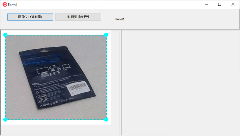
Drag the blue control handles to match the trapezoid or parallelogram area in the image, then click the “Apply Perspective Transform” button.
The corrected image will be displayed in the right pane.